Server:Server Status

Welcome to Joe’s Xbox Xecuter 3 Upgrade Preparation Guide!

I made this update guide for several reasons:
1) I am extremely bored
2) I am excited for the X3 to come out
3) All the hardware pictures posted on Team Xecuter's site have me salivating
4) I love taking things apart and after fixing an old car stereo I'm out of projects.

If you want to understand some backgruond before reading this guide, you should see the initial guide I wrote for installing the Xecuter 2.3b lite here. So, the main differences with the new chip and the old chip are that the new pin header uses all of the holes whereas the old chip left 4 empty, there are 2 solder points on the motherboard to enable HDD and LAN activity LED's, and there are 2 solder points to control the reset on eject feature which can get annoying if you've ever run across it.
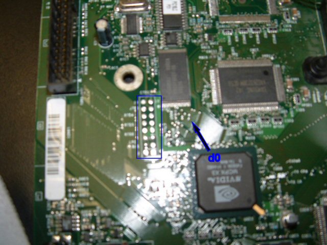
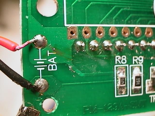
In regards to the tutorial I made before, one obvious problem is that the d0 wire comes through one of the open pin header holes (Hereby to be referred to LPC holes, which is the technical term for BIOS connecter) While it was valid, it was a great way to arrange the wire, but now that we need those holes, we'll have to figure something else out.

X3 Preparation 01
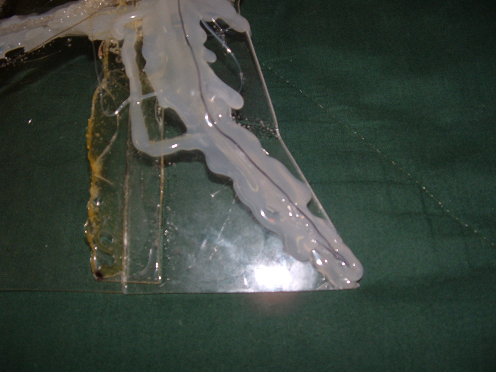
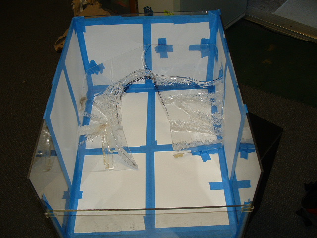
As you can see here, this is what the wire looked like for the X2 mod.
X3 Preparation 02
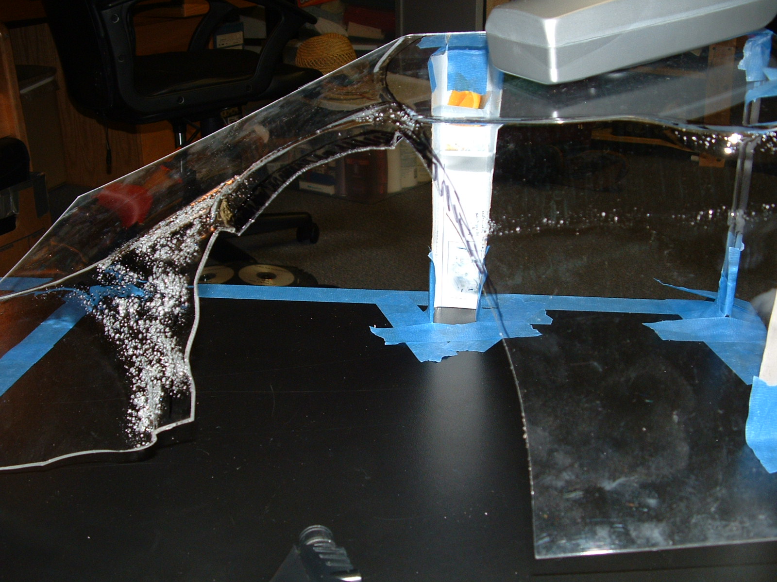
So, now you can see the back of the board, where the d0 is connected. We need to pull the d0 wire out of the hole, so first we need to (on the front) separate the wire I installed from the one coming out of the chip (by lightly touching the soldering iron to the joint and pulling the wires apart) Once done, we'll concentrate on the back.
X3 Preparation 03
Once the tape is removed, you need to pull the grey wire out. This can be tricky, since you don't want to pull the solder joint off. What I did is press firlmy against the part of grey wire about 1/4 inch away from the solder joint, and used a pair of pliers to pull the grey wire through the hole.
X3 Preparation 04
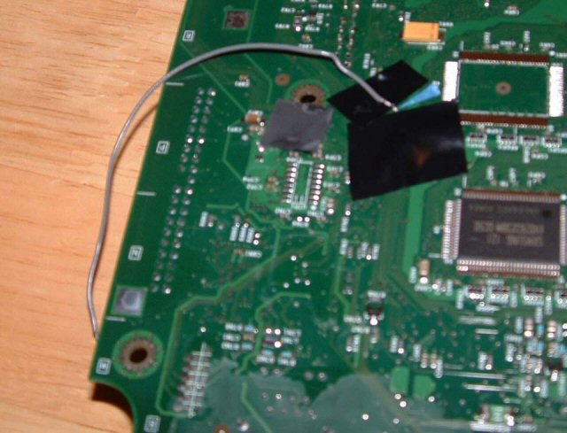
You can see that I left the grey wire really long when I did the initial mod. This paid off, since now I need to re-route it outside the edge of the board.
X3 Preparation 05
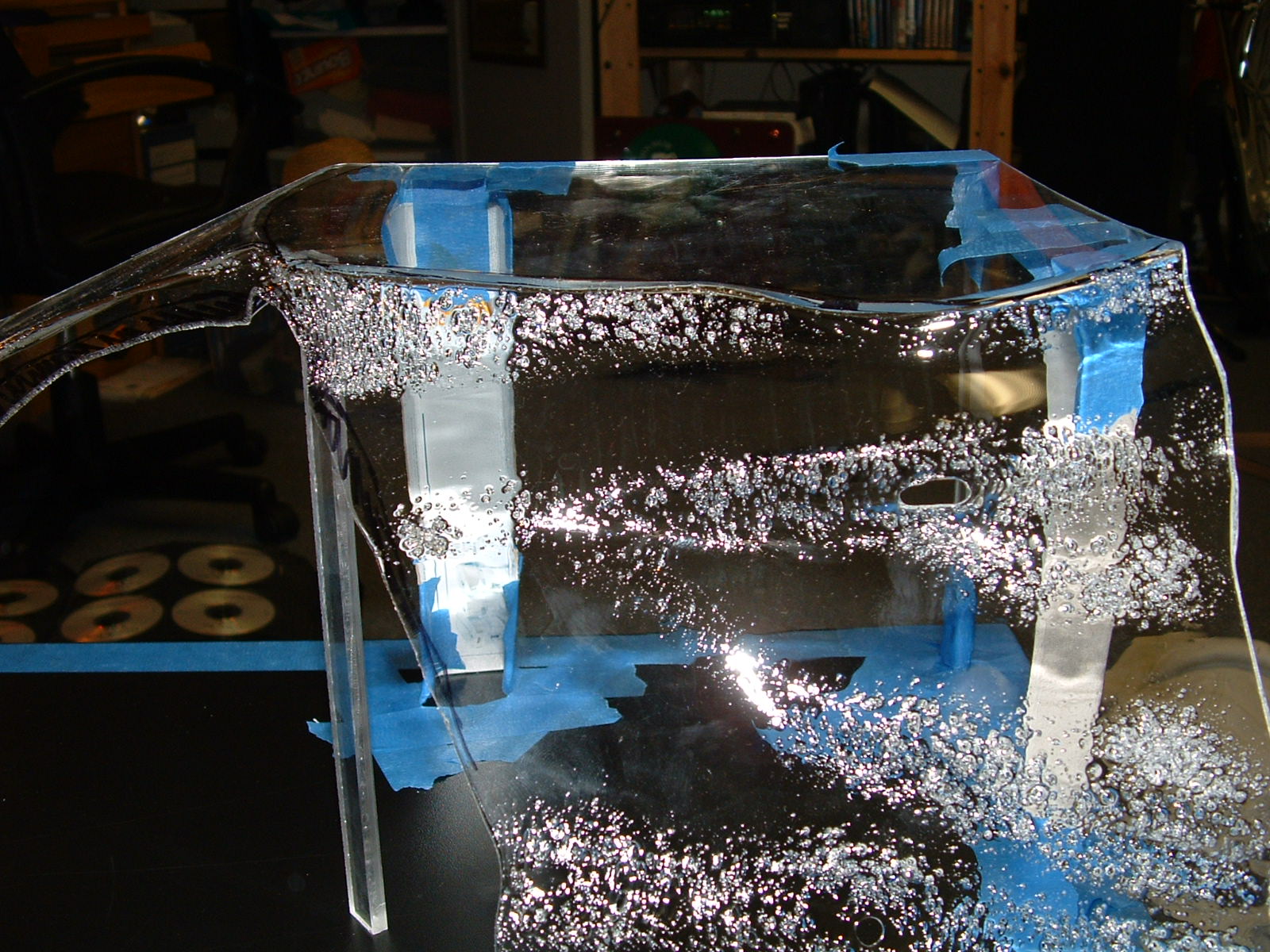
After the wire is out, you want to tape it down pretty quick. This is so you don't accidentally yank it and separate the d0 point, and so that it doesn't flop around and get tangled everywhere.
X3 Preparation 06
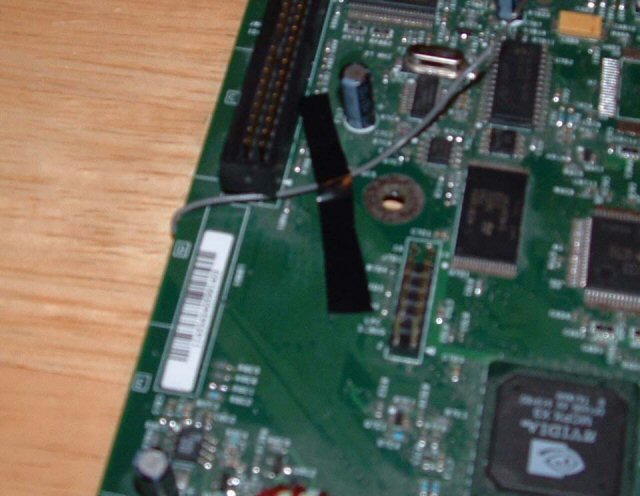
Finally, flip the board back over and tape down the wire on the top. Leave enough room so that you'll be able to attach it to the d0 wire coming out of the port on the chip, which is about what I have left in the picture.
X3 Preparation 07
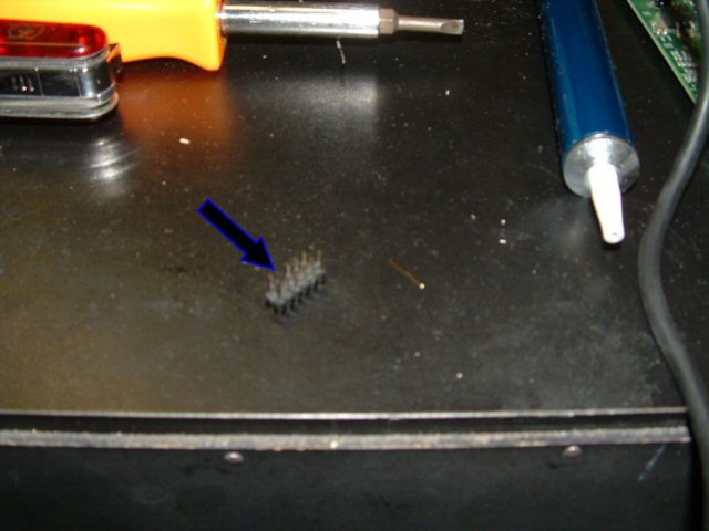
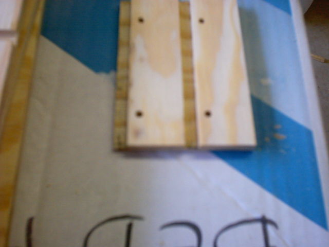
Next is the LPC expander. Rather than de-solder the old pin assembly, I took a spare I had around and made something to fill the 4 empty holes. Here's the spare.
X3 Preparation 08
I removed the 4 pins on an end of it with some needle-nose pliers.
X3 Preparation 09
I then snapped off the black part for the 4 empty holes. It was easy to grip with the pliers and snapped right apart.
X3 Preparation 10
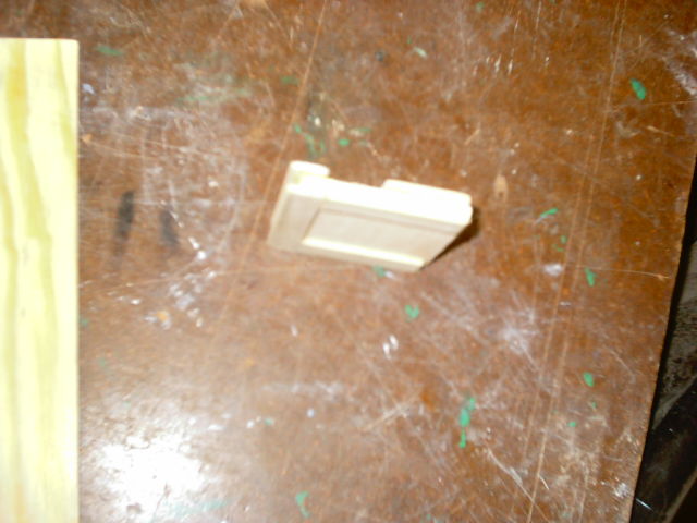
Finally, I put the 4 pins back in the black thing and had a finished pin expander.
X3 Preparation 11
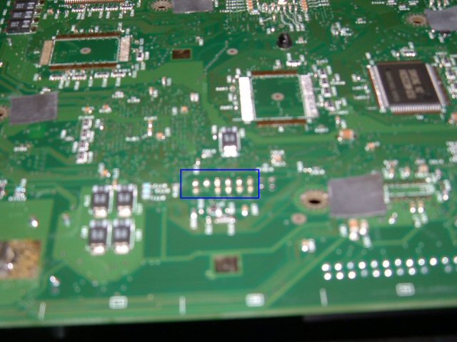
Using the same procedure as I did in the original mod chip installation guide I soldered the new pin assembly into the 4 empty holes. Just to make sure they were straight enough, I put the X2 chip on the new pins and the they fit into the holes.
X3 Preparation 12
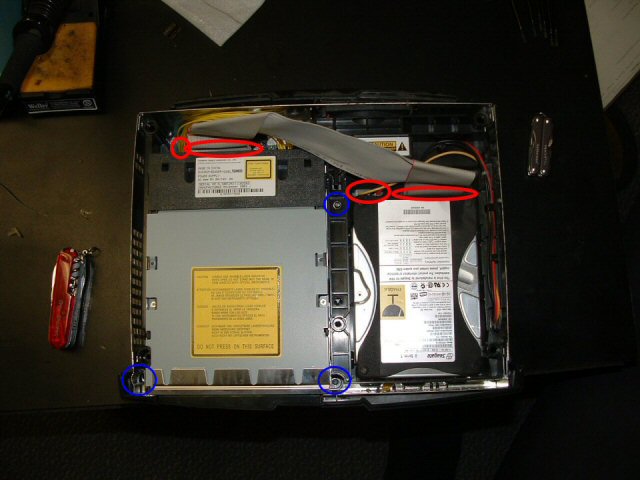
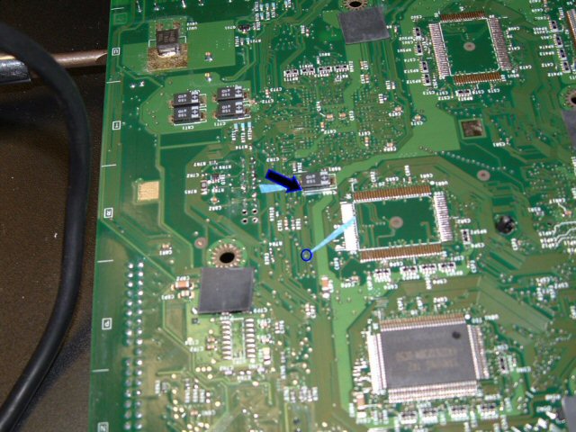
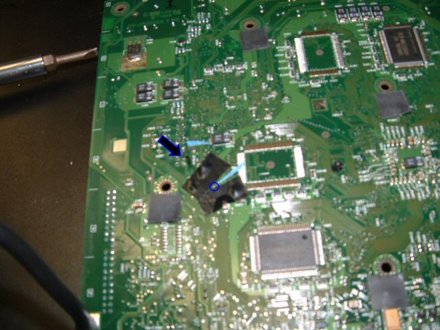
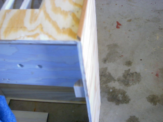
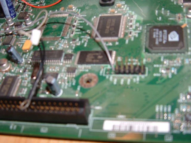
Next are 2 points on the back of the motherboard which will be linked to the LAN and HDD activity LED's. The area of the board I am focusing on is right under the corner nearest the IDE connecter (long and black with about 40 pins) and the LAN port in the back. Find the 2 spots pointed to in the image (Sorry it's so blurry, check the team Xecuter X3 guide for better pics, and mask around them with electrical tape, so you don't accidentally hit anything.
X3 Preparation 13
Because I am doing this with the intention of one day soldering it to a completed X3 chip, I left a lot of extra wire (about 18 inches) and I recommend you do the same, since you can always cut it to accommodate your mod. I soldered the wires so they were facing the edge of the board for easy wrap around to the front, much like the d0 wire. I labled them with some masking tape flags, and taped them down for now.
X3 Preparation 14
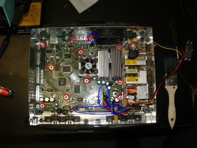
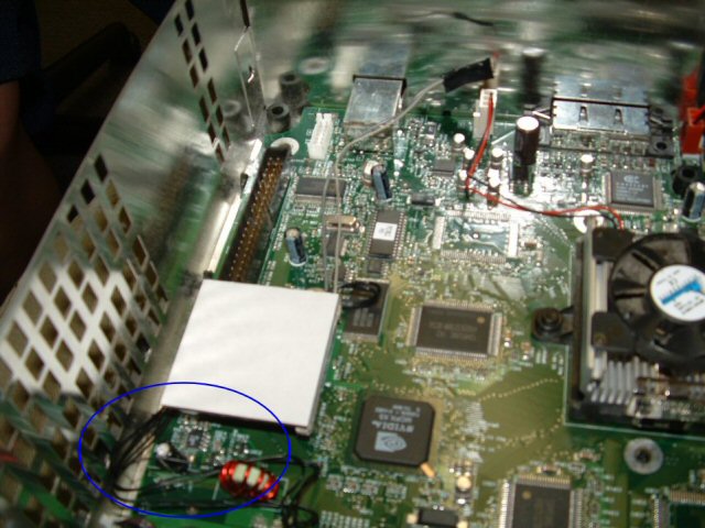
The other 2 wires needed are for the reset and eject fixes which the new chip can control. To do this, you need wires coming out of the button controls to connect to the chip. In the image, I have highlighted which wires coming out of the yellow connector towards the front of the xbox need connections. This was the trickiest part of this project, but what I recommend is taking some long, multi-strand wire, stripping 1/4 of an inch, flattening it out, tinning it with some solder (applying some solder to it so it's more solid than free wires) then trimming it with some scissors so it fits alongside the metal casing in the white plug. Once it fits, slip it in and just apply some solder to the wire, it should take (travel on its own as a liquid to the connection point) and make your wires complete.
X3 Preparation 15
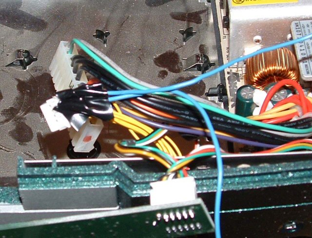
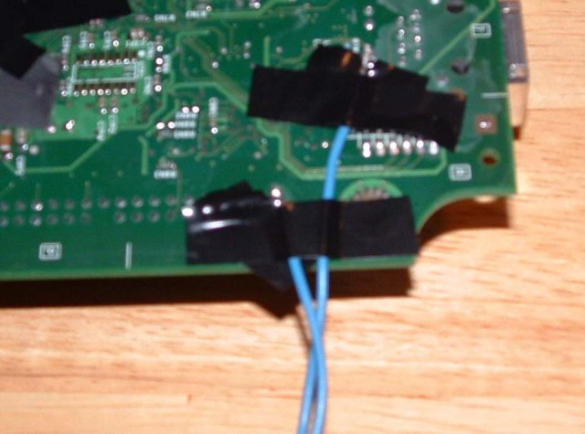
It's hard to see here, but I used electrical tape to fasten the blue wire and its associated yellow wire together. This not only shields it, but makes sure neither wire will be pulled out. I labeled them with masking tape flags and tucked them over where the chip will be installed.

So that's that. I just put the motherboard back in the box, screwed everything in, and put my X2 back in where it belongs. You'll notice if you try it that the X2 won't go all the way on since the d0 connecter gets int he way of the new pins, but it still makes a connection so don't worry. When it's time for X3, it should be a quick, simple process to open the board up, trim and solder the 4 wires, and pop on the pin header. Please feel free to ask me any questions about my guide at my e-mail. Thanks a lot for reading, happy modding!

- - - - - - - - - - - - - - - - - - - - - - - - - - - - - - - - - - - - - - - - - - - - - - - - - - - - - - - - - - - - - - - - - - - - - - - - - - - - - - - - - - - - - - - - - - - - - - - - - - - - - - - - - - - -

Turtle Tank and Dock

As we all know, Jenn and I have a baby named the Baron. Specifically, a baby map turtle named The Baron von Deutschenheim the Second. When we got him, or should I say before we got him, I knew he'd need a home so I made him an awesome one. First, I built the tank itself. Now, you may know where he lives now, unfortunately, dad and I tried to re-caulk this tank and it sprung a series of leaks we never got to finish fixing, so it's in my house in Villa Park accumulating dust. One day though, he'll live in it again.

Dock 01
The tank is made out of 1/4 inch clear acrylic with one side lowered for the filter. The lowered filter position allows for the water to be lower but there still be dry space at top. I used the foil and paper towel method to test for leaks, and she passed awesomely!
Dock 02
This picture is the same, but deleting it would screw up the number order of my pictures.
Dock 03
A close up of the strengthened joint, it's epoxy, silicon caulk, and reinforced acrylic 90 degree bends.
Dock 04
The opposing dropped corner.
Dock 05
So, his royalty will like a place to sit out and bask in the sun as well as a place to hide, like a cave. He also needs to be able to easily get up on it, and it should be pretty. I used some 1/8 inch acrylic to make a custom dock feature. Here's the simple piece I started with.
Dock 06
The first bends, done with a light butane torch.
Dock 07
The acrylic stretches when it is bent so the bends don't have to be straight lines, as you can see. Who knew I was a sculptor too?
Dock 08
I'm inspecting the rig, I want the height to be right above the water line set by the lowered edge, so I made this little rig to hold it steady while I worked.
Dock 09
Preparation for the firing, notice my heat prevention gloves.
Dock 10
BURN!
Dock 11
THE MELTEY FIRE!!! The acrylic bubbles if it gets too hot.
Dock 12
Heating is a slow process.
Dock 13
Pensive.
Dock 14
Slowly taking shape, thanks for takin pics Jenn.
Dock 15
The bubbles are where it's heated up a lot, but they make it easy to expand and bend. It's really starting to take a dropped ramp shape.
Dock 16
The beginnings of the cave.
Dock 17
Beginning the drop side.
Dock 18
The ramp from the front, in formation.
Dock 19
Ok, here's the rock structure, if I do say so myself it turned out spectacular, it looks really natural and flowing.
Dock 20
Again.
Dock 21
Side view, with an extender at the bottom. And a hottie in the background, studying.
Dock 22
This is where my man is gonna sit when he's sunning!
Dock 23
Seems the ramp is too short, think I'll need to extend it.
Dock 24
Closeup on the drop side extension.
Dock 25
Here's the extension on the ramp, with the whole unit installed in the tank. Temporarily, to make sure it fits.
Dock 26
Fits great, sits on little nubs glued to the side of the tank.
Dock 27
The dock out again.
Dock 28
It may look ugly, but this is the extension held on with hot glue and acrylic scraps. It looks better in the end, and I did this knowing it.
Dock 29
More.
Dock 30
More.
Dock 31
Well, I want this thing to look beautiful, so I'm gonna make it look like rock. First, I covered the inside of the tank with laminated paper.
Dock 32
So many repeat pictures!
Dock 33
The dock is in, see it fits. See why soon!
Dock 34
It's in.
Dock 35
So Adam (my awesome resident) and I went to the volleyball courts and stole some janky ass sand.
Dock 36
Using the lid of my small tank as a sieve, we filtered out the bad sand from the good sand.
Dock 37
See the fine nice sand?
Dock 38
This adhesive is used to put countertop laminant down, I laid it on thick.
Dock 39
Me painting the dock in the covered tank.
Dock 40
More cover.
Dock 41
And now do you get it??? It looks like rock since the sand sticks to the glue!
Dock 42
The underside too, which turned out to be a problem. . .
Dock 43
The weight of the sand caused cracks which I had to repair.
Dock 44
Hidden and covered!
Dock 45
Finished, with some stray pieces coming off over time.
Dock 46
The repaired underside.
Dock 47
Supported by nubs.
Dock 48
So here's the beautiful tank with the pic of a turtle in there, all ready to be enjoyed!

- - - - - - - - - - - - - - - - - - - - - - - - - - - - - - - - - - - - - - - - - - - - - - - - - - - - - - - - - - - - - - - - - - - - - - - - - - - - - - - - - - - - - - - - - - - - - - - - - - - - - - - - - - - -

Welcome to Joe’s Xbox Mod Chip Installation Guide!

Here, I'll try to show you the simple process for modifying the Xbox console and adding a mod chip. The chip I am describing is the Xecutor 2.3b lite, but the process should be similar for any chip. First, you need to take your Xbox apart.
X2 Mod 01
Remove the 6 hex nuts with a torx driver t-20. There's a screw under 2 of the labels, write the number you must break through down somewhere, in case it's important. You'll see when you do it. I wrote mine on the same label, with a sharpie. Once the screws are out, remove the cover.
X2 Mod 02
Once in, unplug the ribbon cable to the hard drive and the CD ROM and the motherboard, and unplug the power from the hard drive. There is a yellow wire coming from the CD-ROM, unplug that from the motherboard. There are 3 screws holding the drives in, these are t-10 torx wrenches. Remove them, then remove the drives, hard drive first.
X2 Mod 03
Next, unplug the power, fan, front buttons, and controllers from the motherboard. Unscrew the screws with a t-10 torx.
X2 Mod 04
Carefully remove the mothehrboard from the case. You may need to lift it from the front first, so the plugs in the back slide out. Place it on a smooth, nonconductive surface. We will be focusing on a small area of the board.
X2 Mod 05
We will be doing 2 major soldering projects: The pins for the BIOS upgrade (which are surprisingly here from Microsoft, maybe for testing or future add ons? Let's not complain!) and the d0 point. The d0 point is in a different spot on different versions of the Xbox, and this is a 1.0 version. You can learn about your version and how to distinguish it here, and later on I'll show you exactly where the d0 point is on your board. In the rows of holes, we need to remove the solder. This is a fairly simple procedure if you get a solder sucker, which is about 6 dollars at radio shack. A solder sucker is a spring loaded piston which you can set by pressing down on the spring until it locks, and then with a push of a button make it spring up, creating a vacuum inside. Put the opening over liquid solder (made liquid by heating with the soldering iron) and the solder inside the hole should suck right out.
X2 Mod 06
If done correctly, it looks like this. Don't worry about leaving a little solder in each hole, so long as you think you could push a pin through it, it'll be ok. You'll notice later we don't solder into all holes, but clean them out anyway, it's good practice and who knows, maybe one day a new mod chip will use them for something.
X2 Mod 07
This is the pin header we will be installing. A pin header should come with any mod chip you buy. This is the preferred method for installing mod chips because it allows for ease of exchange (If you decide to upgrade to a new generation chip) and a solid connection. Before we insert this, we must remove a pin, since there is a spot with no hole which must be accounted for.
X2 Mod 08
If you can see, it's the second pin up on the left. This can be easily slid out with a pair of pliers.
X2 Mod 09
Place the pin assembly in the holes, it shold only fit in one place. Tape it down with some masking tape or something, making sure it's all the way in. The tape will later be removed, it's to hold the pin assembly on when we flip the board upside down and solder the pins.
X2 Mod 10
It's blurry, but these are correctly soldered pins from the bottom of the board. You should practice some first, but by touching the top of the pin with some solder and a hot iron, the solder should on its own stick to the metal of the hole and form a little hersy kiss type joint.
X2 Mod 11
This is not part of the Xbox, but it's a better picture of a proper solder joint.
X2 Mod 12
Now, onto the "impossible" part, the d0 point!!! I'm sure everyone has heard how the d0 point is the most difficult thing to deal with ever, and that you'll be trying for days and ruin your Xbox doing it. Remember the picture above? If you look at your hole on your Xbox, you'd swear I'm kidding you about soldering to that tiny spot, but you do indeed need to have a connection to it - or, if you're smart, just make a connection to something already connected to that point. Here is where the d0 point is on the different boards.
X2 Mod 13
If you flip the board over, you can find the spot on the back the hole is connected to, and follow the trace attached to it to find a nice, easy to solder spot. Yes, the bottom blue arrow points to a completely valid d0 point. Surprisingly, most guides don't tell you to do it this way, but this is reality folks, and this is the sinple and solid way to do it. Also, by going from the bottom, you decrease the chance of accidentally pulling the wire out when messing inside the device, making it all the more attractive to solder to. If you don't have the same version as me, just find your d0 point, find where it comes through on the back, and follow it's trace, you'll find something there easier to solder to.
X2 Mod 14
In this picture, I covered the solder points around the d0 point with some electrical tape. This is to ensure I don't accidentally make a connection with something I shouldn't. Also, looking at the holes for the pin header, there's 4 holes we cleaned and didn't use; I put a length of wire through one (which happens to be grey), and the wire I used was pretty snug in that hole. Later on, you'll see that a snug wire is added security so that nothing will tug on the joint you make. The grey wire is hard to see here, but it's on there, sticking up out of the second hole on the right. So, without much ado, I put some excess solder on the exposed tip of the grey wire, I used some pliers to hold the stripped end of wire onto the contact point, heated it with the soldering iron, and when it looked like it fused gave it a light tug to make sure. When I was sure (after 1 try on both the xboxes I did, and no I'm not a pro solderer) I taped over the connection so it didn't touch the bottom. (alternatively, you could put tape on the bottom of the metal in the xbox, so if you ever want to look at your solder joint there isn't tape stuck to it)
X2 Mod 15
So here's the top of the board again, all back in the case. I used the Xecutor 2.3b lite chip, which I like very much. You can follow the grey wire coming out of the hole we cleaned out; I left some of the end of it exposed, and merely twisted the end of it to the exposed end of the little grey wire coming out of the chip (The intended use of that little grey wire is to solder onto the front d0 point, but that's ridiculous) and covered it with electrical tape. There are 2 wire sets plugged into the chip; the one to the ground/d0 wire, and a set of black wires which we will use in a minute. Have both plugged into the chip, and screw the ground hole into the ground screw hole on the motherboard. Notice on the chip there is a black rectangle with holes in it; that will be sliding onto the pins you installed.
X2 Mod 16
Once you are ready, put the chip on the pins. It should look something like this. Notice the black wires coming out of the chip closest to the camera, we'll deal with those next.
X2 Mod 17
With this chip, there is a small control panel and LED that go on the front of your machine. To put them there, unscrew the controller ports from the front of the xbox and move them aside. Feed the end of the black wire through the vent holes in the bottom. This was the trickiest part of the mod for me since I have big stubby fingers. Tweezers are your friend!
X2 Mod 18
This is what the little switch chip looks like once it is installed. The wire through the controller ports comes through and plugs in with no extra wires hanging out, the white backing is peeled off and the stick surface is stuck to the bottom of the console, and the switches and LED are accessible from the front.
X2 Mod 19
Once you put the controller ports back in, it should look something like this, with the wires coming out the bottom of port 1. Finally, we are done!!! Plug everything back in like it was, and you're ready to make things work!!!
X2 Mod 20
To do the final check that your chip is installed correctly, once you've hooked all the internal guts back up, power it up and see if these 2 blue lights are visible from the side of the Xbox with the chip. If both are lit, everything is connected and you should be good to go. If they are not lit, then go back and check your connections, specifically the d0 connection. Keep at it, you'll get it eventually. Happy modding!

- - - - - - - - - - - - - - - - - - - - - - - - - - - - - - - - - - - - - - - - - - - - - - - - - - - - - - - - - - - - - - - - - - - - - - - - - - - - - - - - - - - - - - - - - - - - - - - - - - - - - - - - - - - -

THE SUPERCOMPUTER MOD

  Ok, there's a lot of stuff to know about this. Originally, this computer was a Micron 120Mhz server tower from about 1994. Dad ran his business out of it for many many years, and he got a 2 gig upgrade which made this completely obsolete. I wanted a full tower to be completely unified in my design, and it was perfect for what I wanted. The design and construction took almost a year, but the result is worth it.
  Weighing in at a pristine 78 lbs, this thing turned out to be everything I wanted. When I started, I knew I wanted to cut the clam shell and make doors, which was a new thing. I wanted windows in those doors, and I wanted everything self contained. I had to work when at my parent's house, which is hard when I only go back every so often. Wiring the cables was rough, making new cables of course part of the process, making everything working off the power I had, learning both metal and body and paint work. There's tons of fans all over, lights, internal speakers for the motherboard, internal USB, connections for everything everywhere, and a killer paint job that screams out about my style. It has a DVD burner, a CD burner, a DVD-ROM, an 80 gig HDD, and a 300 gig HDD. There's 3 stage lighting, including 1 sound sensitive light that throbs to my bass! I had to dramatically reshape the holes in the front and back, turn an AT case into an ATX compatible machine, and figure out how to make 2 power supplies work together. I'm sorry I didn't take in progress pics, but it was such a long process it didn't make sense.

Both Computer and I Are Virginal Here
The only pic I can find of the original case, notice the white clamshell ugliness. So much better now.
Super Computer 01
Here's the whole front, from top to bottom there's the Disc drives, then the hard drives, the live drive, the card slot, the USB ports, the switch panels, the internal 10/100 hub, the vents, the base, then the block at the bottom.
Super Computer 02
The back side, notice the cool paint and the base which has the wheels, you can see the back of the power strip down there.
Super Computer 03
The back. Notice 2 power supplies, that's kind of original, the original case had a HDD chassy up there. The fan panel is below that which helps outline the motherboard area, it's artistically sanded aluminum. The original case had all serial and parallel ports as they did back in the day, and that panel covered it up nicely. Below that is the cards, notice how full it is down there. Card list, with updates since the pictures: Vid Card, Sound Card, Ethernet Card (second wired one), Wireless Ethernet card (making 3 internet connections! Yay RIP listener!), the game port for the sound card, the internal USB connector card, and a partridge in a pear tree. Notice the plug in the back, the single plug for the power strip.
Super Computer 04
The top, simply an integrated ipod dock/charger and palm pilot dock and charger and extra battery charger.
Super Computer 05
The switch area. At the top on the right, the power button to the top power supply which powers the 5 port hub, the Disc drives, and the lights. Those need to be on before the other switch, but can be on independently. Below that, there's the fan speed switch on the far left, hi, med, and low. In the middle there's the card reader and USB ports, then the power, reset, HDD LED and PW LED for the main power supply which is hooked to the motherboard, cards, and HDD's. Under that, there's the switch to the 2 stable lights and the one for the sound sensitive light, plus the mic. The dimmer controls the sound sensitivity. The micron logo is kind of a cool touch, since it connects it to it's past life. You know what the hub does, connected to the second wired ethernet card.
Super Computer 06
The fun to look at side. Notice it's a door and not that stupid clamshell. Much prettier and more convenient. You can also see how chaotic it is in there, don't worry, I know intimately.
Super Computer 07
Kind of the boring window, any computer person knows this is the power supplies and the drive backs. NEED TONS OF ROOM!
Super Computer 08
OK, ::takes deep breath:: This is the soyo dragon ULTRA 640+ motherboard with a 2.4 P4 CPU and 1 gig of RAM. The video card in there then was the ATI All in Wonder 8500 DV but since have moved to an ATI ALl in Wonder X800 and it rules. There's the creative Audigy with the Live Drive so my comp is now the full A/V machine, with all HD optical, midi, and composite ins and outs. HOT. The Volcano 7 fan on the CPU is visible and loud. Now, off to the right, you can see some fun stuff. I put 4 USB ports on the inside of the case to plug in the remote receiver for the AIW, the card reader, the palm pilot dock, and the wireless keyboard and mouse receiver. SEE, NO MORE CARRYING ACCESSORIES AROUND. The USB ports on the back of the motherboard, plus the connectors on the card, and the ones for the front panel, that's 10 total plus 3 firewire. WOW.
Super Computer 09
Ok, here's the blue sound sensitive light, it flashes when there's noise.
Super Computer 10
The big bright blue light.
Super Computer 11
The string light in the front that shows through the vent slots. AWESOME.
Super Computer 12
Under the comp in the base, here's the little power strip. So convenient!
Super Computer 13
Ok, I LAN and move a lot, so I was smart enough to put wheels on this thing. Here they are, painted as well.
Super Computer 14
To pull this thing, I have a string with a handle in the front. It sits on a block in the front so it doesn't roll on it's own, you just pull it up a little and it rides on the wheels.

- - - - - - - - - - - - - - - - - - - - - - - - - - - - - - - - - - - - - - - - - - - - - - - - - - - - - - - - - - - - - - - - - - - - - - - - - - - - - - - - - - - - - - - - - - - - - - - - - - - - - - - - - - - -

Wood Case Project

After the cube case, I realized it's not good if you're like me and you move every few months. I set out to make a more standard case, constructed of wood to be strong and durable. Unfortunately I didn't take finished pics, but now that I'm past it's use (I used it for 2 years) I still have it in my closet at home. I'll try to take some pics next time I'm there, I'm sorry I won't have any pics of electronics in it, but it was spectacular.

Wood Case 01
My pristine piece of plywood!
Wood Case 02
Radial arm saw angle 1.
Wood Case 03
Radial arm saw blade.
Wood Case 04
Radial arm saw angle 2.
Wood Case 05
Gross pieces of the case I originally cut.
Wood Case 06
Formation of the box.
Wood Case 07
Marking the bay shelf distances on the chassy wall.
Wood Case 08
Measuring out the width of the chassy shelves against my hard drive chassy.
Wood Case 09
See, it fits pretty!
Wood Case 10
Dad helped me a ton with the cutting, since I only had about a week to make it.
Wood Case 11
From this pic, you can see the first mock up of the case.
Wood Case 12
Front view, notice the 6 5.25 bays and the 2 3.5 bays.
Wood Case 13
Rear view, with the power supply and the card slots, before putting the duct hole in.
Wood Case 14
Wood split when cutting out the card slots, but I ended up ditching this piece anyway.
Wood Case 15
The shelves between the drives were holed out for ventilation.
Wood Case 16
How I made those holes, with a 2 inch hole saw.
Wood Case 17
Second mock up with all the edges cleaned up.
Wood Case 18
You can see that I cleaned up all the holes and made more chassies for the power supply and stuff.
Wood Case 19
Another angle, it's sweet.
Wood Case 20
The cleaned up rear end.
Wood Case 21
Inside of the chassy wall with the grooves and screw holes drilled.
Wood Case 22
Detail of the 3.5 inch bay wall.
Wood Case 23
Duct slot in the back of the case so a duct to the CPU is getting fresh air always.
Wood Case 24
Optional plug for the duct hole, in case I don't like the duct (which I never ended up using).
Wood Case 25
Duct and plug.
Wood Case 26
Detail on back of the plug.
Wood Case 27
Side of plug.
Wood Case 28
All pieces laid out ready for staining.
Wood Case 29
Half on pieces. . .
Wood Case 30
. . .and the other half.
Wood Case 31
Beginning of the white stain process, I stained the inside white.
Wood Case 32
The stain.
Wood Case 33
Unnecessary picture of an intermediate point.
Wood Case 34
Stained chassy being glued together.
Wood Case 35
Stained wood and it's looking good! The white really popped, and lights will reflect color from inside.
Wood Case 36
The finishing nail gun which held the project together in conjunction with some wood glue.
Wood Case 37
Gluing and nailing the chassy in place, using the clamps to hold stuff in place.
Wood Case 38
2 details to notice in this pic, the 1/4 round that was used as the edging on the inside and the beginning of the border on the front to level it off.
Wood Case 39
Bottom border on the front.
Wood Case 40
Acrylic wall and door hinged by tape.
Wood Case 41
Open.
Wood Case 42
Front view with the completed border in the front with is level.
Wood Case 43
Check the screws holding the acrylic on, and the edging inside the case which is nailed and glied down as a frame. It's strong as heck.
Wood Case 44
Stained edge pieces.
Wood Case 45
Late pic of cutting the window.
Wood Case 46
Inside pic of good frame pieces.
Wood Case 47
More structure.
Wood Case 48
Front structure.

- - - - - - - - - - - - - - - - - - - - - - - - - - - - - - - - - - - - - - - - - - - - - - - - - - - - - - - - - - - - - - - - - - - - - - - - - - - - - - - - - - - - - - - - - - - - - - - - - - - - - - - - - - - -